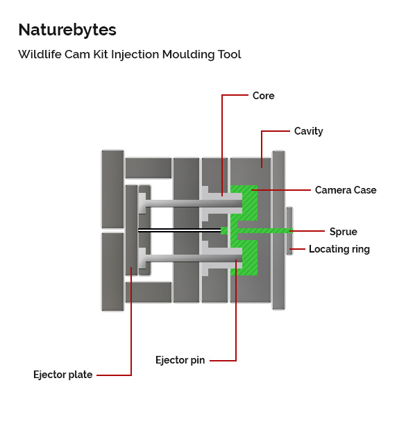
It does this by injecting material – most commonly thermoplastic and thermosetting polymers at high pressure into a “tool”.
The diagram below details the components within our tool. A common analogy is to compare the parts within a tool to that of a car engine to help understand how the moving parts within the tool work. Consider the plates as the engine sump, the core as the pistons, the cavity as the cylinder and the ejections pins are the camshaft and valves. Ultimately, a lot of moving parts manufactured to precision. This YouTube video animates the process.
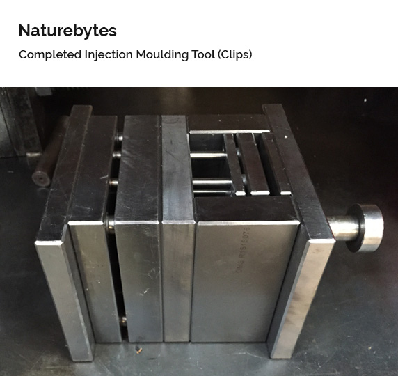
One of the completed Naturebytes tools can be seen below. This tool created the clips that secure the case and was a simple tool to create compared to the case itself.
The tool makers identified that the camera case design would require a tool with a number of moving parts to make the sophisticated hinges, the hole in the base, the rear base clips and the pin holes. An initial difficulty was encountered due to the fact that mould tools are pulled open and close in the same direction (a process called the line of draught), but complications can arise when you need to make shapes or holes at different angles – which our tool required, so a late design change was made to add 12 separate additional moving parts and to split the tool into two separate pieces.
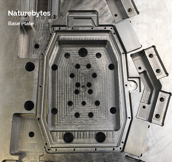
The completed base plate for the Wildlife Cam Kit
Originally, the plan was to have both the cover and the base of the kit in one tool to make the tool and production as cost effective as possible (the process costs tens of thousands of pounds). However, during the tool design stage, mould flow analysis highlighted a potential quality risk known as “in-balancing”. Due to the weight differences between the 2 main components this could have potentially caused a quality issue and a higher chance of “short” mouldings. When the molten plastic is forced into the tool it will fill the biggest voids first and more easily. At the extremities of the tool the plastic has less pressure and struggles to fill the remaining cavity which risks an incomplete product and thus a reject. Therefore additional time was taken to re-design the tools as two separate tools, allowing for the best possible product quality. Subsequently, making 2 tools has taken more time to complete than a single tool.
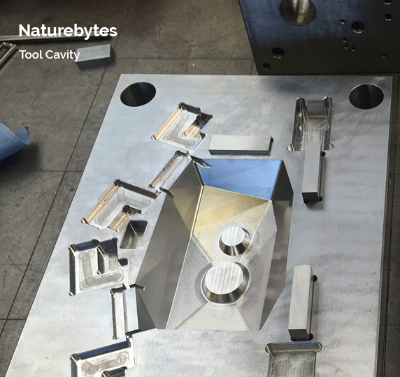
The Wildlife Cam Kit tool cavity
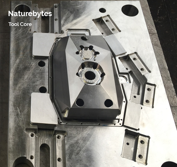
The Wildlife Cam Kit tool core
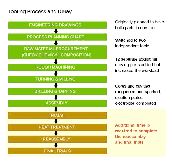
The 12 additional moving parts and the move to two separate tools ensured that the end product was a first rate tool, which it needed to be. The diagram below provides an overview of the complete process to date.

0 Comments